mainmenu
Wide –field Laser Scanning Microscopy for Imaging through The Intact Skull
Imaging in Wave Physics Multi-Wave and Large Sensor Networks 2019
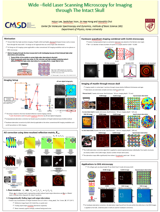
Abstract: We present a novel non-fluorescence-based adaptive-optics optical coherence tomography that can eliminate higher-order aberrations even in the regime of strong multiple scattering of light. With this technique, we demonstrate in vivo high-resolution reflectance imaging of collagen fibers through the intact skull. After compensating the measured phase aberration by using a wavefront control device, high-resolution second harmonic generation images can also be achieved successfully.
2. Results
2.1 Aberration correction using a space-domain time-resolved reflection matrix.
Figure 1. Aberration correction using a space-domain time-resolved reflection matrix. a, Sample geometry. As a test sample, a homemade Siemens star target was placed under two layers of polyethylene terephthalate exhibiting strong higher-order aberrations. b, A set of complex-field images of reflected waves measured at the output plane rout = (xout, yout) for a set of illumination points {rin}. The white x marks indicate the position of the focused illumination. Scale bar: 10 mm. c, Time-resolved reflection matrix R in the position space constructed from the set of measured complex-field images in b. Each image in b was converted to a vector and assigned to the column of R. d, Time-resolved reflection matrix Rkk in the spatial frequency space obtained by applying a two-dimensional Fourier transform at both the columns and rows of R. e, The space-domain matrix Rc converted from Rkk after the application of CLASS algorithm. f, Confocal image obtained from the diagonal elements of R in c, i.e. before aberration correction. g, Aberration-corrected CLASS image obtained from the diagonal elements of the matrix Rc in e. Scale bar: 10 mm. h and i, Phase maps of the sample-induced aberrations at the input and output pupil planes, respectively, obtained by the CLASS algorithm. The input and output aberrations were almost identical as a consequence of the optical reciprocity principle.
2.2 Imaging of collagen fibers located below an intact mouse skull.
Figure 2. Imaging of collagen fibers located below an intact mouse skull. a, Experimental schematic. Collagen matrix was placed under an excised mouse skull. b, OCM image before the aberration correction. Scale bar: 10 mm. c, RMM images combined after applying aberration correction for each of 6x6 patches in b. Color bars in b and c indicate intensity normalized by the maximum intensity in b. d, Aberration map corresponding to each of the 36 patches in b. e, Zoom-in aberration map for the patch marked by a red circle in d. The phase conjugation of this map was displayed on the SLM for hardware aberration correction. Color bars in d and e, phase in radians. f, Conventional OCM image obtained after correcting the aberration indicated by the red circle in d using SLM. f and g, SHG images before and after the aberration correction by the SLM, respectively. The white dashed box in each figure indicates the patch where the physical aberration correction was applied.
References
[1] P Pande. et al. Opt. Lett. 41(14), 3324–3327 (2016)
[2] Kang, S. et al. Nat. Commun. 8, 2157 (2017).
[3] Kang, S. et al. Nat. Photonics 9, 253–258 (2015).
[4] A Badon. et al. Sci. Adv. 2 , e1600370 (2016).

![]()
Tel. +82-62-715-4703~4 / Fax. +82-62-715-4707
Copyright(c) 2014 Center for Relativistic Laser Science at IBS. All Rights Reserved.